How to Calculate Wall Thickness: The Complete Guide
Updated September 16, 2026
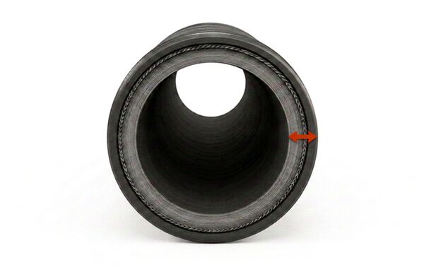
Knowing how to accurately measure and calculate the wall thickness of flexible hoses, ductings, and tubing is a fundamental requirement for designing efficient, reliable, and safe fluid and air transfer systems.
Whether you are sizing suction and delivery lines, calibrating pneumatic tubing, or routing heavy-duty pressure hoses, wall thickness dictates how your system handles mechanical stress, internal pressure, and external vacuum.
You may be specifying chemical transfer lines in a processing plant, installing an extraction duct in a woodworking shop, or engineering hydraulic circuits in an industrial facility; miscalculating wall thickness can result in catastrophic line bursts, unexpected vacuum collapse, flow restriction, or premature fatigue.
This comprehensive guide walks you through everything you need to know about wall thickness: core definitions including Inner Diameter (ID), Outer Diameter (OD), Nominal Diameter (DN), and Nominal Bore (NB); how wall thickness behaves across flexible hoses, ductings, and tubing; the structural role of reinforcements like spring steel and PVC helices; and the mechanical influence of materials and Shore hardness.
What is Wall Thickness?
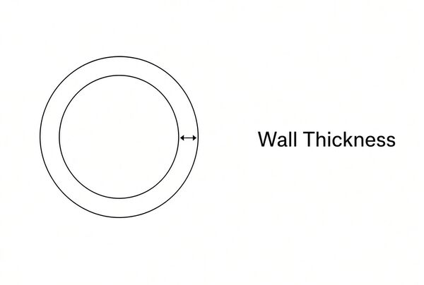
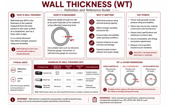
The definition of wall thickness is: The radial distance between the inner surface and the outer surface of a hose, tube, or duct. In mathematical terms, it represents half the difference between the Outer Diameter (OD) and the Inner Diameter (ID). Wall thickness is the primary structural barrier that separates the fluid, air, or abrasive solid inside the line from the ambient operating environment outside.
- A thinner wall thickness provides greater flexibility, lower weight, tighter bend radii, and higher volumetric flow for a given outer diameter.
- A thicker wall thickness provides higher burst pressure resistance, superior vacuum holding capability, enhanced kink resistance, and greater durability against physical abrasion.
Understanding Diameters and Nominal Sizing
To calculate wall thickness accurately, you must understand the distinction between physical dimensions and standardised nominal sizing conventions:
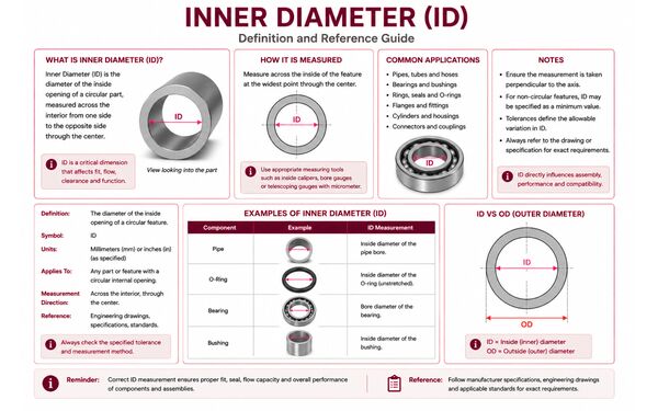
- Inner Diameter (ID): The internal bore diameter measured from inner wall to inner wall. The ID determines the cross-sectional flow area, flow velocity, friction loss, and volumetric capacity.
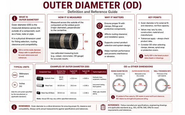
- Outer Diameter (OD): The total external diameter measured from outer wall to outer wall. The OD determines compatibility with push-in fittings, compression fittings, routing clamps, swaged crimp ferrules, and protective sleeves.
- Wall Thickness (WT): The physical cross-section of the tube or hose wall, expressed as:
Wall Thickness = OD - ID2
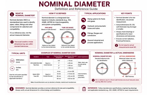
- Nominal Diameter (DN): A metric designating convention (from the French Diamètre Nominal, standardised under ISO 6708) representing the approximate internal diameter in millimetres (e.g., DN 25 corresponds roughly to a 25 mm bore). DN is a dimensionless reference number for matching pipe, hose, and fitting classes—it does not represent a directly measured physical wall or bore dimension.
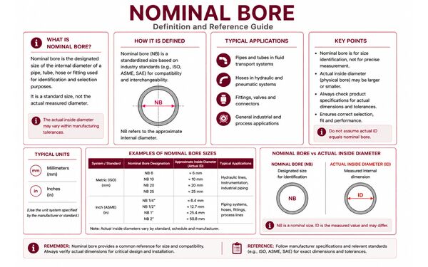
- Nominal Bore (NB): An imperial designator (frequently expressed in inches, e.g., 1" NB) historically based on the pipe's internal flow capacity. Similar to DN, Nominal Bore is an engineering reference figure. Two hoses with the same Nominal Bore can have noticeably different Outer Diameters and wall thicknesses depending on their pressure rating and reinforcement style.
The Science Behind Wall Thickness: Pressure, Stress, and Vacuum
When media flows through a pressurised tube or hose, internal fluid pressure exerts an outward radial force known as hoop stress (circumferential stress) alongside axial (longitudinal) stress. In basic cylindrical pressure vessels and unreinforced tubing, hoop stress is quantified through Barlow’s formula:
P = 2 × S × WTOD
Where:
- P = Internal fluid pressure (bar or psi)
- S = Allowable tensile stress of the material at operating temperature (MPa or psi)
- WT = Wall thickness (mm or inches)
- OD = Outside diameter (mm or inches)
As internal pressure increases, the wall must be thicker or constructed from a material with higher tensile strength to prevent radial dilation and burst failure. Conversely, in suction and delivery applications where external atmospheric pressure exceeds internal line pressure, a thin, unsupported wall will experience compressive buckling and collapse inwards. Here, wall thickness and spiral reinforcement provide structural hoop stiffness to withstand negative pressure.
Why Wall Thickness Varies by Application and Design

Wall thickness is not a uniform metric across fluid handling components. Construction methods, reinforcement architecture, and operating parameters create distinct categories:
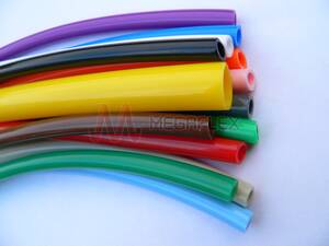
- Tubing: Precision-extruded with a single homogeneous wall or co-extruded multi-layer profile (e.g., metric pneumatic tubing). Dimensions are tightly governed by both ID and OD to ensure leak-free connections in push-in, compression, or flared fittings.
Example: PTFE Tubing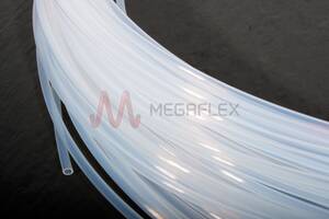
- Suction and Delivery Hose: Heavy-duty flexible hoses designed to operate under both positive working pressure and full negative pressure (vacuum). To prevent vacuum implosion while maintaining routing flexibility, the wall incorporates an embedded spring steel helix or a rigid PVC helix encapsulated within rubber or polymer layers. The overall wall thickness must fully cover and bond with the helix geometry.
Example: Oil S&D Hose

- Pressure Hose: Engineered strictly for medium- to high-pressure discharge. These hoses rely on thick elastomer walls reinforced with high-tensile synthetic textile braids or steel wire spirals to absorb dynamic hydraulic shock loads and pressure spikes.
Example: Shotblast Hose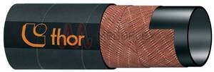

- Layflat Hose: A specialised delivery hose with a collapsible wall construction (typically PVC, nitrile, or polyurethane with woven polyester jackets). In its unpressurised state, the wall lies completely flat, allowing compact roll-up storage. Measuring wall thickness requires a single-wall gauge measurement, as the hose is flat rather than circular when idle.
Example: Blue Layflat Hose

- Ductings: Lightweight, flexible conduits optimised for low-pressure air, fume, and abrasive dust transfer. Wall thicknesses are significantly thinner than standard hoses (often 0.4 mm to 2.0 mm), supported by an integrated spiral helix to keep the duct open under extraction airflows.
Example: Food PU Ducting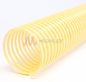

- Clip Ductings: Specialised high-temperature or chemical extraction ducts where the wall material (such as silicone-coated glass fabric, PTFE film, or hypalon) is mechanically clamped into an external metal clip profile (often galvanised or stainless steel) that acts as an external helix. Here, wall thickness refers specifically to the gauge of the clamped fabric or film membrane, while the overall profile thickness is determined by the external clip structure.
Example: Kapton High Temperature Clip Ducting

Material Selection and the Role of Shore Hardness
The required wall thickness is directly tied to the intrinsic mechanical properties of the underlying polymer or elastomer. Material elasticity and resistance to indentation are measured via Shore hardness (Shore A for soft, elastic materials; Shore D for semi-rigid and rigid polymers):
- Silicone (Shore 40A – 70A): Highly flexible and thermally resilient (-60°C to +200°C), but possesses low tensile strength. Unreinforced silicone tubes require thicker walls to withstand even moderate working pressures.
- PVC (Shore 60A – 90A): A versatile, cost-effective thermoplastic. Soft flexible PVC hoses require generous wall thicknesses or internal synthetic textile braiding to manage water pressure, while rigid PVC helices are formulated at higher hardness to supply crush resistance in suction lines.
- Polyurethane (PU) (Shore 70A – 98A / Shore 55D): Exceptional tear strength and up to five times the abrasion resistance of standard rubber. Because of its mechanical resilience, PU tubing and ducting can be manufactured with substantially thinner walls while outperforming thicker PVC in high-wear abrasive media transfer.
- Viton / FKM (Shore 60A – 80A): A high-performance fluoroelastomer engineered for extreme chemical and acid exposure. Its wall thickness is calibrated to balance chemical permeation resistance against high material cost.
- Nylon / Polyamide (Shore 60D – 75D): A semi-rigid engineering plastic with high tensile strength and burst resistance. High Shore D hardness allows nylon tubing to feature comparatively thin walls while maintaining working pressures of 15 to 30+ bar in pneumatic brake and fuel circuits.
- PTFE (Shore 55D – 65D): Chemically inert fluoropolymer with an ultra-low coefficient of friction and a wide temperature envelope (-200°C to +260°C). Thin-wall PTFE tubing provides structural hoop strength and universal chemical resistance without requiring excess wall mass.
Why is Wall Thickness Important?
Overlooking wall thickness during system design leads to operational inefficiencies, safety hazards, and mechanical failures:
- Pressure Containment & Safety: If the wall thickness is too thin for the operating pressure, hoop stress exceeds material yield strength, resulting in ballooning, wall thinning, and catastrophic bursting. In pressurised steam, chemical, or hydraulic lines, ruptures present severe safety hazards to personnel and equipment.
- Resistance to Vacuum Collapse: In suction processes (e.g., bilge pumping, grain transfer, or vacuum extraction), atmospheric pressure crushes an undersized wall inward. Proper wall thickness combined with an embedded spring steel or PVC helix prevents flat-spotting and line choking.
- Flow Dynamics and Pressure Drop: Choosing a hose with excessive wall thickness for a fixed outside diameter reduces the internal bore (ID). Restricting the ID accelerates flow velocity, increases turbulence, causes friction-induced head loss, and strains pumps and compressors.
- Kink Resistance and Bend Performance: Wall thickness works in tandem with bend radius. A wall that is too thin without spiral reinforcement will buckle and kink when curved; a wall that is excessively thick resists kinking but creates a stiff line that strains fittings and increases installation difficulty.
- Wear Allowance in Abrasive Slurry and Dust Systems: When conveying wood chips, gravel, grain, or slurry, abrasive particles continuously scour the internal wall. Specifying an adequate inner wall gauge provides a sacrificial wear barrier, directly extending the service life of the duct or hose.
How to Calculate Wall Thickness

Lets get to it, calculating and verifying wall thickness requires a combination of geometric formulas, nominal conversions, and precise physical measurement techniques. This is how it's done:
1. The Fundamental Geometric Formulas
When physical dimensions are known, wall thickness is derived using simple geometry:
Wall Thickness: WT = OD - ID2Outer Diameter: OD = ID + (2 × WT)
Inner Diameter: ID = OD - (2 × WT)
Example Calculation:
An extruded pneumatic polyurethane tube has a measured Outer Diameter of 12.0 mm and an Inside Diameter of 8.0 mm:
WT = (12.0 mm - 8.0 mm) / 2 = 4.0 mm / 2 = 2.0 mm
2. Calculating Layflat Hose Wall Thickness
Because layflat delivery hoses do not maintain an open circular bore when depressurised, you cannot directly measure the ID with standard internal calipers while the hose is idle. Instead:
- Measure the flat width (Wf) of the unpressurised hose.
- Calculate internal diameter:
ID ≈ 2 × Wfπ
- Measure the total flattened double-wall thickness (T2w) with a micrometer and divide by 2 to determine single wall thickness:
WT = T2w2
3. Engineering Calculation: Sizing Wall Thickness for Working Pressure
To determine the minimum required wall thickness (WTmin) for an unreinforced plastic tube based on system pressure, rearrange Barlow’s equation and apply an appropriate safety factor (SF, typically 3:1 or 4:1):
WTmin = (Pmax × OD × SF) / (2 × St)
Where Pmax is peak operating pressure, OD is outside diameter, SF is safety factor, and St is the material's yield strength at operating temperature.
Tools and Measurement Techniques
Physical measurement must account for the flexibility and deformability of elastomeric walls:
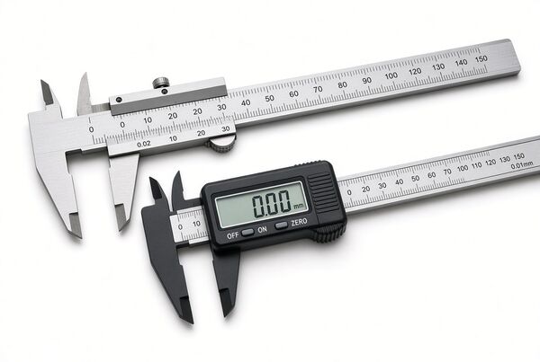
- Vernier or Digital Calipers: Ideal for semi-rigid tubing (Nylon, PTFE). When measuring soft materials (Silicone, low-durometer PVC), caliper jaws can compress the wall, producing an artificially thin reading. Apply minimal jaw force or measure optical cross-sections.
- Ball-End Micrometers: Specifically designed with a spherical anvil that fits against the curved inner diameter of a cut tube, ensuring point contact without flattening the wall.
- Ultrasonic Wall Thickness Gauges: Non-destructive measurement tools that emit high-frequency acoustic pulses through the outer cover to read reflections from the inner wall. Crucial for measuring rigid composite hoses or inspecting installed lines for internal wear without cutting the assembly.
Wall Thickness Tolerances and Concentricity
Manufacturing extrusions are subject to dimensional variations governed by standards such as BS EN ISO 13000-1 (for fluoropolymers) or ISO 3302-1 (for rubber tolerances). A key parameter is concentricity (or wall eccentricity): the outer and inner circles of a hose may not share an identical centre line, leading to uneven wall thickness around the circumference. Always take multiple measurements at 90° intervals around the cross-section to verify minimum wall compliance.
Working Within Wall Thickness Limits: Practical Selection Rules
- Match Hoses to Fittings: Push-in pneumatic fittings seal on the tube’s Outside Diameter (OD). If you select a heavy-wall tube with an oversized OD, it will not seat inside the fitting cartridge. Conversely, hose tails and barbs seal against the Inside Diameter (ID); excessive wall thickness can prevent standard crimp collars or interlocking ferrules from swaging correctly.
- Account for Thermal Softening: As temperatures rise, thermoplastics and elastomers lose tensile modulus. A wall thickness that withstands 10 bar at 20°C may expand or rupture at 60°C unless appropriately de-rated or reinforced with high-tensile cords.
- Account for Reinforcement Geometry: In spiral steel helix suction hoses, measure wall thickness between the helix crests (the thinnest membrane point) to assess baseline permeation and tear resistance, not just over the reinforced rib.
- Avoid Twisting During Installation: Torsional strain during routing causes localised wall thinning on one side and pinching on the other, dramatically reducing burst pressure.
- Inspect Sacrificial Liners: Regularly measure the remaining wall thickness on slurry, shotblast, or grain-transfer lines. Replace sections once internal wear exceeds 30% to 50% of the initial inner tube thickness.
Conclusion
Wall thickness is a core engineering specification across flexible hoses, industrial ductings, and precision tubing. Far from being a passive dimension, it dictates structural burst pressure, vacuum resistance, volumetric flow efficiency, and working durability. By mastering the relationships between Inner Diameter (ID), Outer Diameter (OD), and nominal classifications like DN and NB, you can design fluid systems that perform reliably under challenging operating conditions.
Always verify your calculations against manufacturer specifications and engineering data sheets. Reinforcements such as spring steel wire spirals, rigid PVC helices, and textile braiding alter pressure capabilities and bend dynamics across different materials—from soft silicones and flexible polyurethanes to rigid polyamides and inert PTFE. A correctly calculated, properly specified wall thickness protects your equipment investment, optimises flow, and ensures workplace safety.

Frequently Asked Questions (FAQ) - How to Calculate Wall Thickness
Q: What is the exact formula for calculating wall thickness?
A: The basic geometric formula is Wall Thickness = (OD - ID) / 2. If you know the ID and wall thickness, the OD is calculated as OD = ID + (2 × Wall Thickness).
Q: What is the difference between Nominal Bore (NB) and Inner Diameter (ID)?
A: Inner Diameter (ID) is the actual physical measurement of the internal tube opening. Nominal Bore (NB) is an imperial standardised sizing designation (e.g., 2" NB) used to match pipes and fittings. While NB is close to the internal dimension, the actual physical ID will vary based on the pressure rating and wall thickness class of the hose.
Q: How does Nominal Diameter (DN) relate to wall thickness?
A: Nominal Diameter (DN) is a metric reference number (e.g., DN 50) roughly corresponding to an internal diameter of 50 mm. DN does not define wall thickness; instead, different hoses sharing the same DN can have thin, standard, or heavy wall thicknesses depending on their structural reinforcement and pressure capabilities.
Q: Why do suction and delivery hoses require reinforced helices?
A: Under suction, negative pressure causes external atmospheric pressure to push inward against the hose wall. Without structural reinforcement, flexible polymer walls collapse flat. Integrating a high-tensile spring steel wire helix or rigid PVC helix provides hoop stiffness, keeping the bore fully open during high-vacuum extraction.
Q: How do you measure the wall thickness of a layflat hose?
A: A layflat hose collapses into a flat band when depressurised. To determine wall thickness, measure the total thickness of the flattened double-wall assembly with a micrometer and divide by two. Alternatively, measure single-wall thickness directly at the open end of a clean square cut.
Q: What is the difference between ducting wall thickness and hose wall thickness?
A: Industrial ductings are engineered for air, fume, and light dust transfer, featuring thin walls (typically 0.4 mm to 1.5 mm) supported by an external or embedded wire helix for maximum flexibility and weight savings. Hoses are built with substantially thicker, multi-ply textile or wire-reinforced walls designed to contain high internal liquid pressures or severe mechanical abuse.
Q: How does Shore hardness affect wall thickness requirements?
A: Shore hardness reflects a material’s resistance to deformation. Softer materials (low Shore A durometer, such as silicone or soft PVC) have lower tensile modulus and require thicker walls to contain pressure. Harder materials (high Shore D durometer, such as nylon or PTFE) exhibit high tensile strength, allowing thinner walls to achieve the same or higher working pressure ratings.
Q: What is a clip ducting, and how is its wall thickness specified?
A: Clip ducting is constructed by mechanically clamping flexible technical fabrics (e.g., neoprene-coated glass, silicone, or PTFE) into an external metal spiral clip. The wall thickness corresponds strictly to the gauge of the fabric or film membrane (often 0.3 mm to 0.8 mm), while the outer profile diameter is determined by the external metal clip.
Q: Can temperature changes alter the effective wall thickness or pressure rating?
A: While physical wall thickness changes only slightly via thermal expansion, elevated temperatures soften polymers, reducing their tensile strength and modulus. As a result, safe working pressure drops as temperature rises, requiring pressure de-rating factors even though the physical wall thickness remains virtually identical.
Q: How can I measure wall thickness without cutting an installed hose?
A: Use an ultrasonic wall thickness gauge. By applying a couplant gel to the exterior of the hose and placing the ultrasonic transducer on the surface, the gauge measures the time acoustic sound waves take to travel through the wall and reflect off the inner surface, providing an accurate, non-destructive measurement.
Get in Touch
Need expert assistance calculating wall thickness, verifying pressure ratings, or choosing between flexible hose, ducting, and precision tubing? Our technical team is ready to assist with sizing enquiries, pressure calculations, and material recommendations. Browse our product range or contact our technical sales desk today to support your fluid and air transfer systems.Looking for a quote? Contact our technical team today at sales@megaflex.co.uk!